
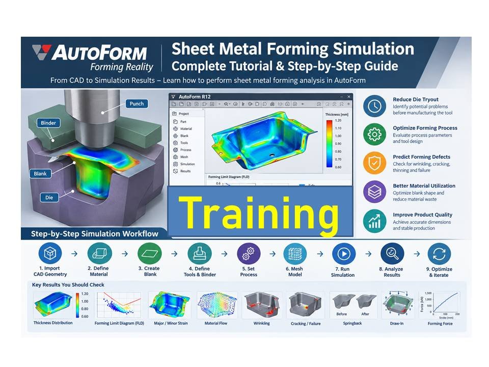
AutoForm Sheet Metal Forming Simulation: Complete Tutorial and Step-by-Step Guide
AutoForm R12 Sheet Metal Forming Simulation: 10-Step Complete Tutorial, AutoForm Sheet Metal Forming Simulation: Sheet metal forming simulation has become an important part of automotive body engineering, die design, process planning, and manufacturing. Before manufacturing expensive stamping dies and starting physical tryouts, engineers can use simulation software to predict forming problems such as wrinkling, cracking, thinning, excessive stretching, springback, and material failure.
START AUTOFORM TRAINING → 🎯 MASTER AUTOFORM — JOIN FREE
AutoForm is one of the widely used CAE solutions for sheet metal forming simulation. It can be used to evaluate forming feasibility, optimize forming processes, analyze stamping operations, and reduce the number of physical die tryouts.
In this tutorial, we will explain how to perform a basic sheet metal forming simulation in AutoForm, from importing CAD geometry and defining material properties to analyzing forming ressults.
What Is AutoForm Sheet Metal Forming Simulation?
AutoForm is a CAE softwarre platform developed specifically for sheet metal forming and related manufacturing processes.
The software allows engineers to simulate the behavior of sheet metal during operations such as:
- Deep drawing
- Stamping
- Stretch forming
- Bending
- Flanging
- Cutting and trimming
- Springbacck analysis
- Hot forming
- Roll forming
- Multi-stage forming
The main objective of simulation is to identify potential manufacturing problems before the physical tool is manufactured.
For example, a simulation can indicate whether a component is likely to develop:
- Cracks
- Wrinkles
- Excessive thinning
- Insufficient forming
- Surface defects
- Springback
- Material failure
- Draw-in problems
This information can then be used to modify the forming process or die design.
START AUTOFORM TRAINING → 🎯 JOIN FREE

Why Use AutoForm for Sheet Metal Simulation?
Traditional stamping development often requires several rounds of die tryout.
A typical process may involve:
CAD Design → Die Manuffacturing → Tryout → Measurement → Modification → Re-tryout
Each die modification can require significant time and cost.
Simulation changes this approach by allowing engineers to evaluate the process virtually.
Major advantages include:
1. Reduce die tryout
Potential forming problems can be identified before manufacturing the final tool.
2. Optimize the forming process
Engineers can evaluate different draw directions, blank shapes, binder conditions, and forming stages.
3. Predict forming defects
🚀 Checkout These Career-Boost Kits
- 📘 APQP Document 100+ – Click Here
- 📊 Production PPC 90+ Documents PPT – Click Here
- 📑 Six Sigma Format – Click Here
- 🎯 Dream Job Kit – Click Here
- 📂 60+ PPT Pack – Click Here
- 🗂️ HR Formats 100000+ – Click Here
- ✅ ISO 9001:2015 Toolkit – Click Here
- ⚙️ IATF (A–Z All Formats) – Click Here
- 📄 Resume Templates 700+– Click Here
Simulation can highlight areas where cracking, wrinkling or excessive thinning may occur.
4. Optimize material utilization
Blank development and nesting can help reduce material consumption.
5. Evaluate springback
Springback analysis can help engineers compensate the die geometry.
6. Improve product quality
Potential manufacturing problems can be addressed during the engineering stage.
AutoForm Sheet Metal Forming Simulation Workflow
A typical AutoForm simulationn workflow can be summarized as:
CAD Geometry
↓
Import Part
↓
Define Material
↓
Define Blank
↓
Define Tools
↓
Define Process
🚀 Checkout These Career-Boost Kits
- 📘 APQP Document 100+ – Click Here
- 📊 Production PPC 90+ Documents PPT – Click Here
- 📑 Six Sigma Format – Click Here
- 🎯 Dream Job Kit – Click Here
- 📂 60+ PPT Pack – Click Here
- 🗂️ HR Formats 100000+ – Click Here
- ✅ ISO 9001:2015 Toolkit – Click Here
- ⚙️ IATF (A–Z All Formats) – Click Here
- 📄 Resume Templates 700+– Click Here
↓
Mesh / Model Preparation
↓
Run Simulation
↓
Analyze Forming Results
↓
Modify Process or Geometry
↓
Run Simulation Again
This iterative process is commonly used durinng stamping process development.
Step 1: Prepare the CAD Model
Before starting the simulation, the component CAD data should be prepared properly.
Common CAD formats used in sheet metal engineering include:
- STEP
- IGES
- Parasolid
- CATIA
- NX
- SolidWorks
- Other supported CAD formats
The imported model should represennt the required sheet metal component surface.
Before simulation, check:
- Surface continuity
- Gaps
- Duplicate surfaces
- Incorrect normals
- Sharp edges
- Unwanted geometry
- Part orientation
- Units
A clean CAD model makes the simulation setup easier and reduces errors.
Step 2: Start a New AutoForm Project
Open AutoForm and create a new project.
Depending on the AutoForm version and installed modules, the exact menu names may differ.
The general workflow is:
New Project → Import Geometry → Define Component → Define Material → Define Process
🚀 Checkout These Career-Boost Kits
- 📘 APQP Document 100+ – Click Here
- 📊 Production PPC 90+ Documents PPT – Click Here
- 📑 Six Sigma Format – Click Here
- 🎯 Dream Job Kit – Click Here
- 📂 60+ PPT Pack – Click Here
- 🗂️ HR Formats 100000+ – Click Here
- ✅ ISO 9001:2015 Toolkit – Click Here
- ⚙️ IATF (A–Z All Formats) – Click Here
- 📄 Resume Templates 700+– Click Here
AutoForm versions such as R7, R8, R9, R10, R11 and R12 may have differences in interface layout and available functions, but the basic simulation methodology remains similar.
Step 3: Import the Part Geometry
Import the component CAD file into AutoForm.
After importing the geometry, inspect the component carefully.
Check the:
- Part orientation
- Surface quality
- Coordinate system
- Sheet metal thickness
- Forming direction
- Component dimensions
If necessary, repair or simplify the geometry before proceeding.
For example, very small features that do not influence forming behavior may be removed from the simulation model.
Step 4: Define Sheet Metal Material
Material definition is one of the most important steps in a forming simulation.
The simulation needs information about how the sheet material behaves under deformation.
Typical material parameters include:
- Material grade
- Sheet thickness
- Young’s modulus
- Poisson’s ratio
- Yield strength
- Tensile strength
- Stress-strain curve
- Anisotropy parameters
- Forming limit information
Examples of materials used in automotive stamping include:
- Mild steel
- IF steel
- HSLA
- AHSS
- DP steel
- Aluminum alloys
- Stainless steel
The material data should be as accurate as possible.
Using incorrect material data can produce misleading simulation results.
Step 5: Define Sheet Thickness
Enter the actual sheet thickness used for the component.
For example:
Material: Mild Steel
Thickness: 1.2 mm
The correct thickness is important because it affects:
- Forming force
- Drawability
- Thinning
- Wrinkling
- Failure prediction
- Springback
Always verify the thickness against the actual part drawing or material specification.
Step 6: Define the Blank
The next step is to define the sheet blank.
The blank represents the initial piece of sheet metal before forming.
There are several approaches to determining the blank.
🚀 Checkout These Career-Boost Kits
- 📘 APQP Document 100+ – Click Here
- 📊 Production PPC 90+ Documents PPT – Click Here
- 📑 Six Sigma Format – Click Here
- 🎯 Dream Job Kit – Click Here
- 📂 60+ PPT Pack – Click Here
- 🗂️ HR Formats 100000+ – Click Here
- ✅ ISO 9001:2015 Toolkit – Click Here
- ⚙️ IATF (A–Z All Formats) – Click Here
- 📄 Resume Templates 700+– Click Here
Initial Blank
A simple rectangular or approximate blank can be used for early process studies.
Developed Blank
AutoForm can be used to calculate a developed blank based on the component geometry.
The blank should provide enough material to form the entire component while avoiding unnecessary material waste.
Blank optimization is particularly important for automotive stamping because even small reductions in blank size can produce significant material savings in mass production.
Step 7: Define the Forming Tools
For a typical stamping operation, the main tools are:
- Punch
- Die
- Binder / Blank Holder
The exact tooling arrangement depends on the manufacturing process.
For a deep drawing operation, the basic setup can be represented as:
Blank → Binder → Die → Punch
During forming, the punch moves relative to the die and forces the sheet into the required shape.
Step 8: Define the Forming Direction
The forming direction determines how the part is formed.
The engineer should evaluate whether the selected direction is suitable for the component.
Important considerations include:
- Draw depth
- Draw beads
- Undercuts
- Material flow
- Tool accessibility
- Part geometry
- Flange requirements
Incorrect forming direction can cause severe forming problems.
Step 9: Define Binder and Blank Holder Conditions
The binder controls the movement of material into the die cavity.
Binder conditions have a major influence on:
- Wrinkling
- Material flow
- Thinning
- Cracking
- Draw-in
If binder force is too low, excessive material may flow into the cavity and create wrinkles.
If binder force is too high, material flow can become restricted and may result in excessive thinning or cracking.
Therefore, binder force must be optimized.
Step 10: Define Friction and Lubrication
Friction between the sheet and forming tools affects material flow.
The simulation therefore requires appropriate friction conditions.
🚀 Checkout These Career-Boost Kits
- 📘 APQP Document 100+ – Click Here
- 📊 Production PPC 90+ Documents PPT – Click Here
- 📑 Six Sigma Format – Click Here
- 🎯 Dream Job Kit – Click Here
- 📂 60+ PPT Pack – Click Here
- 🗂️ HR Formats 100000+ – Click Here
- ✅ ISO 9001:2015 Toolkit – Click Here
- ⚙️ IATF (A–Z All Formats) – Click Here
- 📄 Resume Templates 700+– Click Here
Important contact pairs include:
- Blank / punch
- Blank / die
- Blank / binder
Actual friction depends on:
- Material
- Tool surface
- Lubricant
- Production conditions
- Surface roughness
Using realistic friction assumptions improves simulation accuracy.
Step 11: Create the Finite Element Mesh
AutoForm uses a finite element-based approach to calculate sheet deformation.
The sheet geometry is divided into elements.
The mesh needs to provide enough resolution to capture important forming behavior.
A very coarse mesh may fail to accurately represent small features.
A very fine mesh can increase computational requirements.
AutoForm provides automated meshing capabilities that make sheet metal simulation considerably easier than manually creating a traditional FE model.
Step 12: Define the Forming Process
Now define the actual manufacturing sequence.
For a basic deep drawing operation, the sequence could be:
- Load blank
- Position blank
- Close binder
- Apply binder force
- Move punch
- Form component
- Release tools
- Analyze results
For a multi-operation stamping process, the sequence may include:
OP10 → OP20 → OP30 → OP40
For example:
OP10: Drawing
OP20: Trimming
OP30: Flanging
OP40: Re-striking
OP50: Final inspection
The exact process depends on the component and die design.
🚀 Checkout These Career-Boost Kits
- 📘 APQP Document 100+ – Click Here
- 📊 Production PPC 90+ Documents PPT – Click Here
- 📑 Six Sigma Format – Click Here
- 🎯 Dream Job Kit – Click Here
- 📂 60+ PPT Pack – Click Here
- 🗂️ HR Formats 100000+ – Click Here
- ✅ ISO 9001:2015 Toolkit – Click Here
- ⚙️ IATF (A–Z All Formats) – Click Here
- 📄 Resume Templates 700+– Click Here
Step 13: Run the AutoForm Simulation
Once the model has been completely defined, start the simulation calculation.
Before running the calculation, perform a setup check.
Verify:
- Part geometry
- Material
- Thickness
- Blank
- Tool geometry
- Binder
- Punch
- Die
- Process sequence
- Friction
- Boundary conditions
After confirming the setup, start the calculation.
Simulation time depends on:
- Part size
- Mesh size
- Number of elements
- Number of forming operations
- Computer hardware
- Simulation settings
Step 14: Analyze Thickness Reduction
One of the most important simulation results is sheet thickness.
During forming, some regions become thinner while others may remain close to their original thickness.
For example:
Initial thickness = 1.2 mm
After forming:
Local thickness = 0.95 mm
The percentage thinning can be calculated as:
Thinning % = (Initial Thickness − Final Thickness) / Initial Thickness × 100
For the example:
Thinning = (1.2 − 0.95) / 1.2 × 100
Thinning ≈ 20.8%
High thinning areas should be investigated carefully because they may indicate a risk of cracking or failure.
Step 15: Check Forming Limit Diagram
The Forming Limit Diagram (FLD) is an important tool for evaluating sheet metal formability.
The FLD helps engineers identify whether the material is operating within an acceptable forming region.
Typical results may indicate:
🚀 Checkout These Career-Boost Kits
- 📘 APQP Document 100+ – Click Here
- 📊 Production PPC 90+ Documents PPT – Click Here
- 📑 Six Sigma Format – Click Here
- 🎯 Dream Job Kit – Click Here
- 📂 60+ PPT Pack – Click Here
- 🗂️ HR Formats 100000+ – Click Here
- ✅ ISO 9001:2015 Toolkit – Click Here
- ⚙️ IATF (A–Z All Formats) – Click Here
- 📄 Resume Templates 700+– Click Here
- Safe forming
- Marginal forming
- Wrinkling
- Necking
- Failure
The exact limits depend on the material and forming conditions.
If the simulation shows a critical region close to or beyond the forming limit, the process should be reviewed.
Possible solutions include:
- Reducing binder force
- Increasing binder force
- Changing draw bead conditions
- Modifying blank shape
- Changing forming direction
- Increasing die radius
- Increasing punch radius
- Changing material
- Adding a forming operation
Step 16: Check for Wrinkling
Wrinkling occurs when compressive stresses cause the sheet to buckle.
Typical locations include:
- Flanges
- Binder regions
- Deep-drawn walls
- Areas with excessive material flow
Simulation can help identify areas susceptible to wrinkling before physical stamping.
If excessive wrinkling occurs, engineers can investigate:
- Binder force
- Draw bead location
- Blank size
- Blank shape
- Tool geometry
- Material flow
Step 17: Check for Cracking
Cracking is one of the most serious stamping defects.
Cracks can occur when the material experiences excessive tensile deformation.
Typical causes include:
- Excessive draw depth
- High binder force
- Small tool radius
- Insufficient material flow
- Incorrect blank shape
- High friction
- Poor material formability
AutoForm simulation can identify high-risk areas so the forming process can be modified before tool manufacturing or production.
Step 18: Check Springback
After the forming tools are released, the sheet may partially return toward its original shape.
This phenomenon is called springback.
Springback is especially important for:
- High-strength steel
- Advanced high-strength steel
- Aluminum
- Large body panels
- Structural components
Springback can result in dimensional deviations from the nominal CAD geometry.
AutoForm can be used to simulate springback and evaluate the resulting dimensional deviation.
Engineers can then develop compensation strategies for the tooling.
Step 19: Evaluate Draw-In
Draw-in is another important result in sheet metal forming simulation.
It describes how much material moves into the die cavity during forming.
Draw-in measurements can be compared with:
🚀 Checkout These Career-Boost Kits
- 📘 APQP Document 100+ – Click Here
- 📊 Production PPC 90+ Documents PPT – Click Here
- 📑 Six Sigma Format – Click Here
- 🎯 Dream Job Kit – Click Here
- 📂 60+ PPT Pack – Click Here
- 🗂️ HR Formats 100000+ – Click Here
- ✅ ISO 9001:2015 Toolkit – Click Here
- ⚙️ IATF (A–Z All Formats) – Click Here
- 📄 Resume Templates 700+– Click Here
- Simulation results
- Tryout measurements
- Production measurements
If simulation and physical tryout show significant differences, engineers should review the process assumptions, including:
- Friction
- Material properties
- Binder force
- Tool geometry
- Blank geometry
Step 20: Optimize the Simulation
The first simulation is rarely the final simulation.
If problems are detected, modify the process and run another calculation.
For example:
Problem: Excessive Wrinkling
Possible changes:
- Increase binder force
- Modify draw beads
- Change blank shape
- Improve material restraint
Problem: Cracking
Possible changes:
- Reduce binder force
- Increase punch/die radius
- Improve material flow
- Modify blank geometry
- Change forming sequence
Problem: Excessive Springback
Possible changes:
- Modify forming geometry
- Add restriking
- Change process sequence
- Apply springback compensation
Example: Basic Deep Drawing Simulation
Consider a simple automotive sheet metal component.
Input
Material: Steel
Thickness: 1.2 mm
Operation: Deep Drawing
Process:
Blank → Binder → Punch → Die
The simulation workflow would be:
1. Import component CAD
↓
2. Define material
↓
3. Enter sheet thickness
↓
🚀 Checkout These Career-Boost Kits
- 📘 APQP Document 100+ – Click Here
- 📊 Production PPC 90+ Documents PPT – Click Here
- 📑 Six Sigma Format – Click Here
- 🎯 Dream Job Kit – Click Here
- 📂 60+ PPT Pack – Click Here
- 🗂️ HR Formats 100000+ – Click Here
- ✅ ISO 9001:2015 Toolkit – Click Here
- ⚙️ IATF (A–Z All Formats) – Click Here
- 📄 Resume Templates 700+– Click Here
4. Create blank
↓
5. Define punch and die
↓
6. Define binder
↓
7. Define friction
↓
8. Create mesh
↓
9. Define punch stroke
↓
10. Run forming simulation
↓
11. Check thickness
↓
12. Check FLD
↓
13. Check wrinkles
↓
🚀 Checkout These Career-Boost Kits
- 📘 APQP Document 100+ – Click Here
- 📊 Production PPC 90+ Documents PPT – Click Here
- 📑 Six Sigma Format – Click Here
- 🎯 Dream Job Kit – Click Here
- 📂 60+ PPT Pack – Click Here
- 🗂️ HR Formats 100000+ – Click Here
- ✅ ISO 9001:2015 Toolkit – Click Here
- ⚙️ IATF (A–Z All Formats) – Click Here
- 📄 Resume Templates 700+– Click Here
14. Check failure
↓
15. Evaluate draw-in
↓
16. Run springback simulation if required
↓
17. Modify process if necessary
↓
18. Finalize the process
AutoForm Simulation Results You Should Always Check
After completing a simulation, engineers should not look at only one result.
Important results include:
1. Thickness Distribution
Used to identify thinning and thickening.
2. Forming Limit Diagram
Used to evaluate forming safety.
3. Major and Minor Strain
Used to understand deformation behavior.
4. Material Flow
Used to understand how the blank moves during forming.
5. Wrinkling
Used to identify compressive deformation and buckling risk.
6. Cracking / Failure
Used to identify areas where the material may fail.
7. Draw-In
Used to compare material movement around the component.
8. Springback
Used to evaluate dimensional deviations after unloading.
9. Forming Force
Useful for determining whether the selected press and process are appropriate.
🚀 Checkout These Career-Boost Kits
- 📘 APQP Document 100+ – Click Here
- 📊 Production PPC 90+ Documents PPT – Click Here
- 📑 Six Sigma Format – Click Here
- 🎯 Dream Job Kit – Click Here
- 📂 60+ PPT Pack – Click Here
- 🗂️ HR Formats 100000+ – Click Here
- ✅ ISO 9001:2015 Toolkit – Click Here
- ⚙️ IATF (A–Z All Formats) – Click Here
- 📄 Resume Templates 700+– Click Here
Common AutoForm Simulation Problems and Solutions
Problem 1: Simulation Shows Cracking
Check:
- Binder force
- Material properties
- Friction
- Tool radius
- Blank shape
- Draw depth
- Material flow
Do not immediately assume that the material is defective.
The process conditions should be reviewed first.
Problem 2: Excessive Wrinkles
Check:
- Binder force
- Draw beads
- Blank size
- Material flow
- Tool geometry
The objective is to achieve controlled material flow without creating excessive tensile deformation.
Problem 3: Excessive Thinning
Investigate:
- Local strain concentration
- Punch radius
- Die radius
- Binder force
- Friction
- Material properties
Increasing the forming radius or improving material flow may reduce local thinning.
Problem 4: Springback Is Too High
Springback is strongly influenced by material strength and forming history.
Potential solutions include:
- Tool compensation
- Over-bending
- Additional restriking
- Process modification
- Geometry compensation
AutoForm Tutorial for Beginners
If you are new to AutoForm, do not start with a complicated automotive body panel.
Start with a simple component.
A good learning sequence is:
Level 1 – Basic Part
Learn:
- Import CAD
- Define material
- Define blank
- Create tools
- Run simulation
- Read results
Level 2 – Deep Drawing
Learn:
- Binder
- Draw beads
- Material flow
- FLD
- Thickness analysis
Level 3 – Multi-Operation Stamping
Learn:
- OP10
- OP20
- OP30
- Trimming
- Flanging
- Re-strike
Level 4 – Springback
Learn:
- Springback calculation
- Deviation analysis
- Compensation
Level 5 – Advanced Process Optimization
Learn:
- Blank optimization
- Binder force optimization
- Draw bead optimization
- Process sequence optimization
- Robustness analysis
Important AutoForm Skills for Sheet Metal Engineers
If your goal is to work professionally in automotive stamping simulation, focus on these areas:
Sheet Metal Fundamentals
Understand:
🚀 Checkout These Career-Boost Kits
- 📘 APQP Document 100+ – Click Here
- 📊 Production PPC 90+ Documents PPT – Click Here
- 📑 Six Sigma Format – Click Here
- 🎯 Dream Job Kit – Click Here
- 📂 60+ PPT Pack – Click Here
- 🗂️ HR Formats 100000+ – Click Here
- ✅ ISO 9001:2015 Toolkit – Click Here
- ⚙️ IATF (A–Z All Formats) – Click Here
- 📄 Resume Templates 700+– Click Here
- Yielding
- Plastic deformation
- Strain
- Stress
- Anisotropy
- Work hardening
- Formability
Stamping Process
Understand:
- Drawing
- Stretching
- Bending
- Flanging
- Trimming
- Piercing
- Re-striking
Die Design
Understand:
- Punch
- Die
- Binder
- Draw beads
- Addendum
- Draw direction
- Tool radii
Simulation
Learn:
- Mesh
- Material cards
- FLD
- Thickness
- Wrinkling
- Failure
- Springback
- Forming force
AutoForm Simulation vs Physical Tryout
The objective of simulation is not necessarily to completely replace physical tryout.
Instead, simulation helps reduce uncertainty before the physical tool reaches the tryout stage.
A typical development approach is:
CAD Design
↓
AutoForm Simulation
↓
Process Optimization
↓
Die Design
↓
Die Manufacturing
↓
Tryout
🚀 Checkout These Career-Boost Kits
- 📘 APQP Document 100+ – Click Here
- 📊 Production PPC 90+ Documents PPT – Click Here
- 📑 Six Sigma Format – Click Here
- 🎯 Dream Job Kit – Click Here
- 📂 60+ PPT Pack – Click Here
- 🗂️ HR Formats 100000+ – Click Here
- ✅ ISO 9001:2015 Toolkit – Click Here
- ⚙️ IATF (A–Z All Formats) – Click Here
- 📄 Resume Templates 700+– Click Here
↓
Measurement
↓
Simulation/Process Correlation
↓
Final Production
This approach can reduce development time and improve the probability of achieving a successful first tryout.
Tips for Accurate AutoForm Simulation
For better simulation results:
Use accurate material data
Material cards should represent the actual production material whenever possible.
Use realistic friction conditions
Friction has a significant effect on material flow.
Use correct sheet thickness
Even small differences can influence forming results.
Validate tool geometry
Incorrect punch or die surfaces can produce misleading results.
Do not ignore process conditions
Binder force, draw beads and forming speed can influence the results.
Compare simulation with tryout data
If physical tryout data is available, compare:
- Draw-in
- Thickness
- Failure location
- Wrinkle location
- Springback
- Forming force
This is an important part of simulation validation.
AutoForm Sheet Metal Forming Simulation – Frequently Asked Questions
What is AutoForm used for?
AutoForm is used for sheet metal forming simulation, process engineering, die development, forming feasibility, springback analysis and optimization of stamping processes.
Is AutoForm difficult to learn?
The basic workflow can be learned relatively quickly, but becoming proficient requires knowledge of sheet metal forming, die design, material behavior and simulation analysis.
Can AutoForm simulate deep drawing?
Yes. Deep drawing is one of the common applications of sheet metal forming simulation.
Can AutoForm predict cracks?
AutoForm can evaluate forming behavior and identify regions where the material may exceed its forming limits, helping engineers identify potential failure locations.
Can AutoForm simulate wrinkles?
Yes. The software can be used to evaluate wrinkling behavior and investigate process parameters that influence material flow.
🚀 Checkout These Career-Boost Kits
- 📘 APQP Document 100+ – Click Here
- 📊 Production PPC 90+ Documents PPT – Click Here
- 📑 Six Sigma Format – Click Here
- 🎯 Dream Job Kit – Click Here
- 📂 60+ PPT Pack – Click Here
- 🗂️ HR Formats 100000+ – Click Here
- ✅ ISO 9001:2015 Toolkit – Click Here
- ⚙️ IATF (A–Z All Formats) – Click Here
- 📄 Resume Templates 700+– Click Here
Can AutoForm calculate springback?
Yes, springback analysis is an important application of AutoForm.
What CAD files can be imported?
The exact supported formats depend on the AutoForm version and installed modules. Common engineering exchange formats include STEP and IGES, along with native CAD formats supported by the software.
What should I learn before AutoForm?
A basic understanding of sheet metal forming, stamping dies, material properties, CAD geometry and manufacturing processes is highly recommended.
Conclusion AutoForm Sheet Metal Forming Simulation
AutoForm sheet metal forming simulation provides engineers with a powerful way to evaluate stamping processes before expensive physical die tryouts.
A basic simulation workflow is:
Import CAD → Define Material → Define Blank → Define Tools → Define Process → Mesh → Run Simulation → Analyze Results → Optimize Process → Validate
The most important part of learning AutoForm is not simply knowing which buttons to click. A good simulation engineer must understand why material flows in a particular direction, why wrinkles occur, why cracks develop, how binder force affects forming, and how die geometry influences springback and dimensional accuracy.
Start with simple components and gradually progress to deep-drawing parts, multi-operation stamping, springback and complete automotive body components.
With practical experience, AutoForm can become a valuable tool for sheet metal process engineering, die development, automotive stamping and manufacturing optimization.
AutoForm, AutoForm R12, AutoForm Tutorial, AutoForm Sheet Metal Forming, Sheet Metal Forming Simulation, Sheet Metal Simulation, Stamping Simulation, Sheet Metal Stamping, AutoForm Simulation Tutorial, AutoForm Training, AutoForm Software, AutoForm CAE, Sheet Metal Forming, Deep Drawing Simulation, Stamping Die Simulation, Die Design, Automotive Stamping, Automotive Sheet Metal, Forming Simulation, Finite Element Analysis, FEA, FLD Analysis, Forming Limit Diagram, Springback Analysis, Wrinkling Analysis, Crack Prediction, Thickness Analysis, Material Flow, Draw Bead, Binder Force, Blank Development, Blank Optimization, Automotive Body Engineering, Tool and Die Engineering, Press Tool Design, Stamping Process, Sheet Metal Engineering, CAE Simulation, Automotive CAE, AutoForm Training Tutorial, AutoForm Beginner Tutorial, AutoForm R12 Tutorial